Database schemas
Ready-made database schemas
From release v2.4.0 of the Delft Municipal Data Model (Dutch: Gemeentelijk Gegevensmodel, abbreviated GGM) onwards, a complete set of DDL files (Data Definition Language) is also available — 488 DDLs in total, automatically generated using a batch version of the UML Database Generator (which will soon be released to a wider audience). This batch generator processes all relevant diagrams and exports the corresponding DDL scripts per diagram in several database formats:
- MySQL
- MSSQL
- Oracle
- PostgreSQL
This gives you ready-made schemas for these common databases. The DDLs are intended for developers, data architects and administrators who want to apply the GGM in their own systems or environments. Thanks to this set, it is now possible to work with the GGM data models without using Enterprise Architect — fully tool-independent. The DDL files can be loaded or modified directly with standard SQL tools and editors. Note: this is an early version of the generator. Some imperfections may still occur in the generated files. Feedback is welcome.
You will find the DDLs for the listed databases in the ddl directory of the release directory.
Code generation based on the GGM
If you want to generate DDL yourself with Enterprise Architect, the GGM ships with a set of code-generation templates for use within Enterprise Architect to generate Data Definition Language (DDL). With this you can directly create tables in an RDBMS. Various templates are available for generating database tables and program code (for example: Python, C# and Java). Code generation works for all supported RDBMSs, except for some specific items such as enumerations. We have developed those for:
- Oracle
- MySQL (untested)
- We warmly invite developers to use these and improve their suitability for the GGM.
The supplied templates are extensions to the standard templates of Enterprise Architect, as part of the Code Template Framework.
Installing the code-generation templates
- Download the file CodegeneratieTemplates.xml.
- Start Enterprise Architect.
- (Optional) Create a new project.
- Choose Import Reference Data.
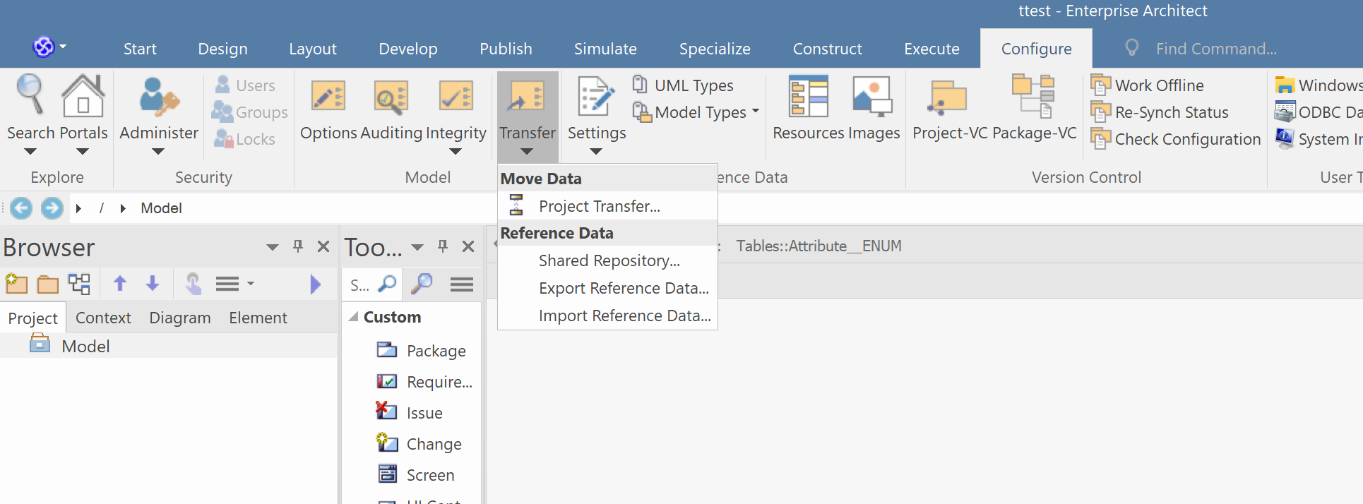
Screenshot (in Dutch / Enterprise Architect UI): the "Import Reference Data" option.
5. Select the just-downloaded CodegeneratieTemplates.xml, select all templates and press Import.
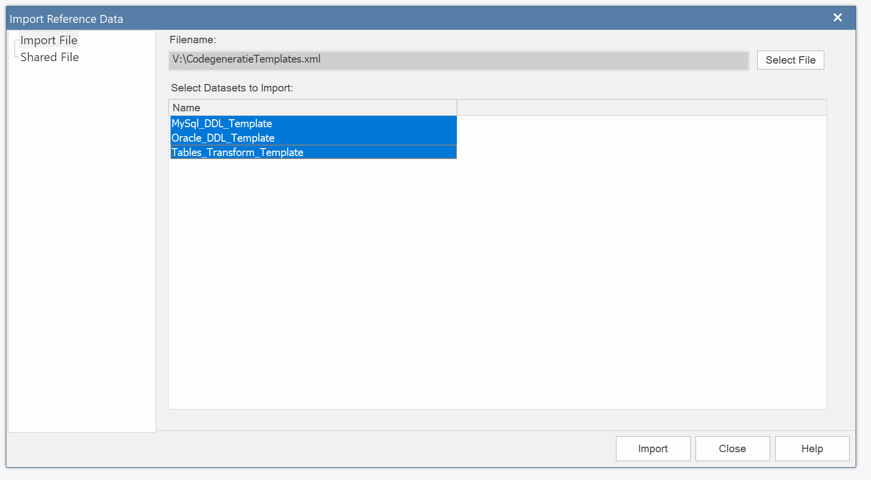
Screenshot: selecting all templates in the import dialog.
6. The templates are ready to use; you find them under Transform.
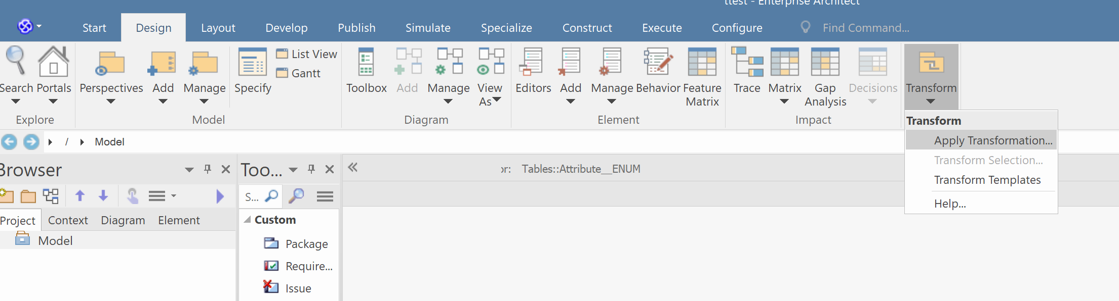
Screenshot: the imported templates available under the Transform menu.
7. Done!
Using the code-generation templates
Generating DDL from the GGM consists of two steps:
- Transforming the logical model into a logical table representation.
- Generating DDL from the logical table representation.
Before you start
First make sure your project has, alongside the GGM, a place where you can write the tables. We use a separate node next to the root node — in the example, the folder <<DataModel>> Tables/Ruimte/Afval.
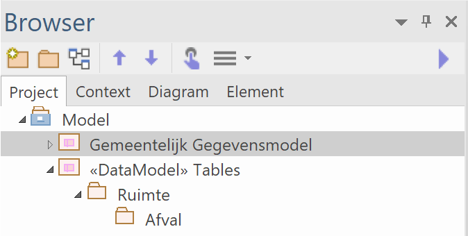
Screenshot (in Dutch / Enterprise Architect UI): folder structure for generated tables.
Then make sure the default RDBMS is selected in Enterprise Architect. Go to Preferences.
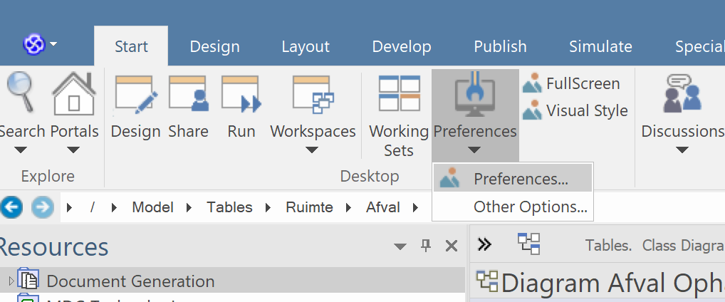
Screenshot: the Preferences menu.
Then under Source Code Engineering / Code Editors choose Default Database. In our example, Oracle.
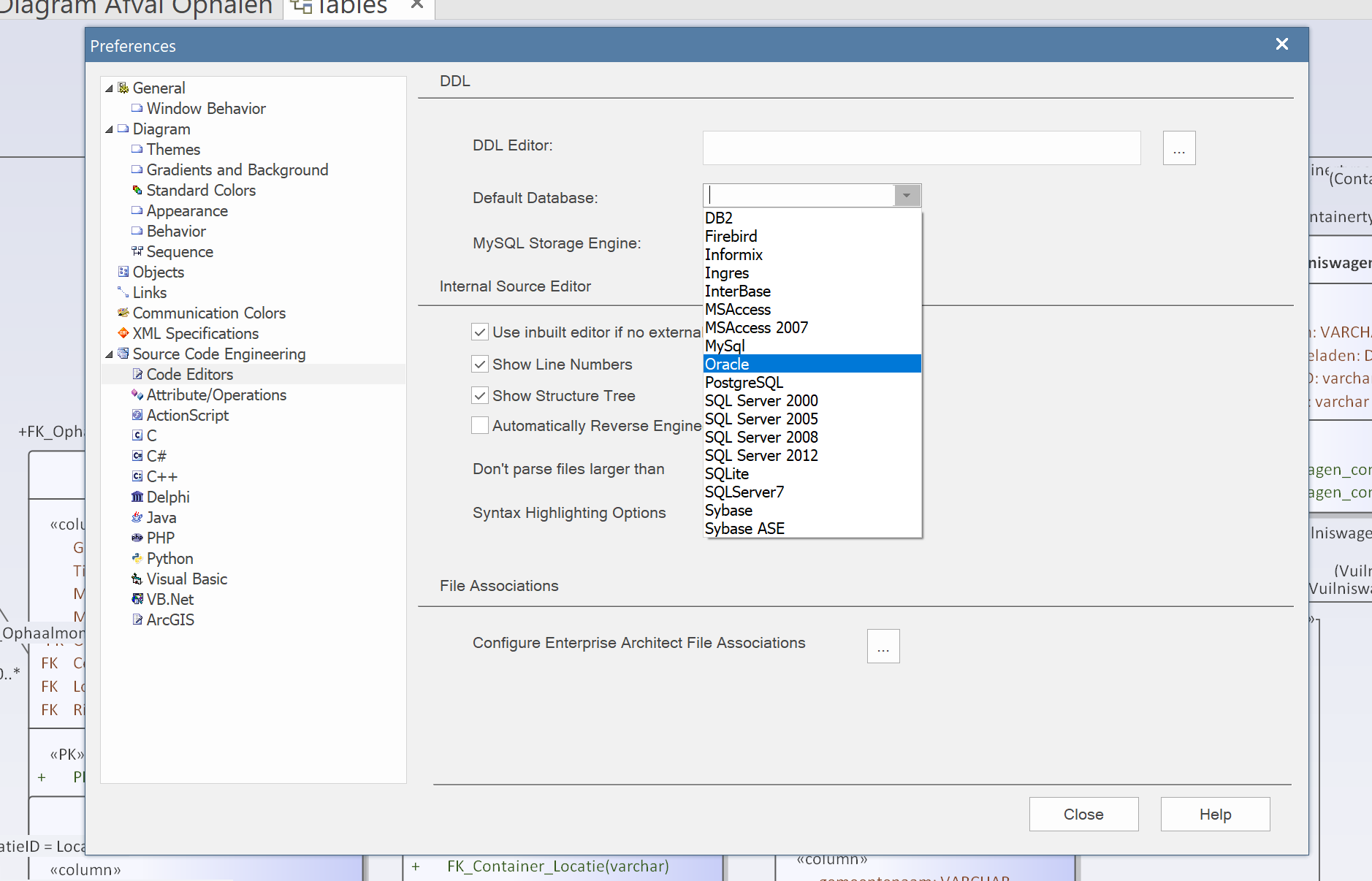
Screenshot: setting Oracle as the default database.
Steps to generate DDL
To generate DDL, take the following steps:
1. Select the part of the model you want to generate. In the example, the folder Gemeentelijk Gegevensmodel/Ruimte/Afval/Model. You can also select the desired object types in a diagram.
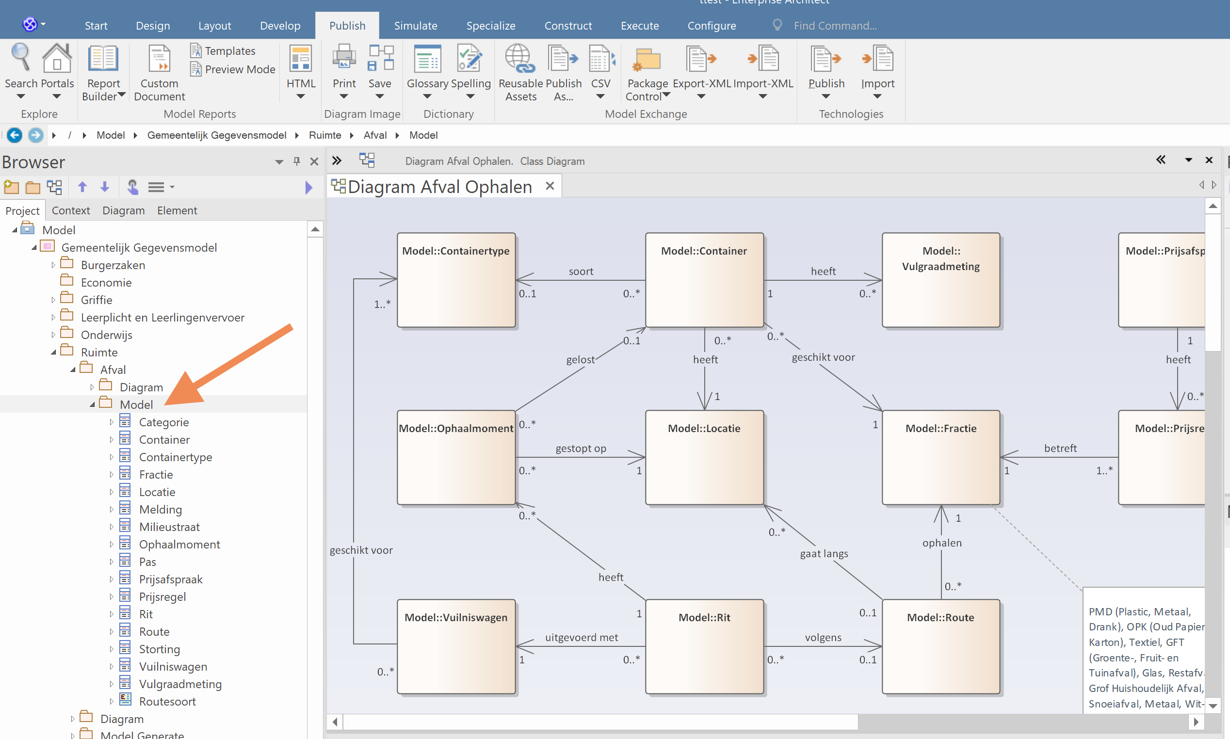
Screenshot: the model folder selected for generation.
2. For the first step in generation, choose Apply Transformation.
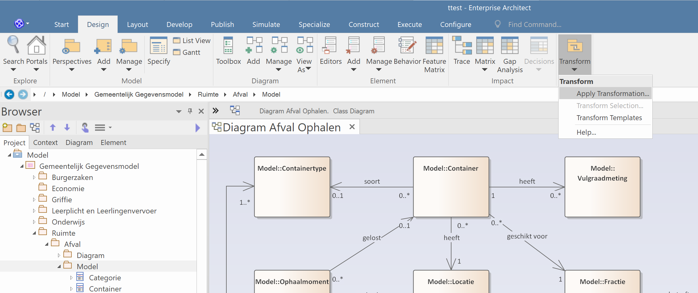
Screenshot: the Apply Transformation menu option.
3. On the right side of the popup, select Tables in the Transformations area. Make sure all object types that should be generated are selected on the left side.
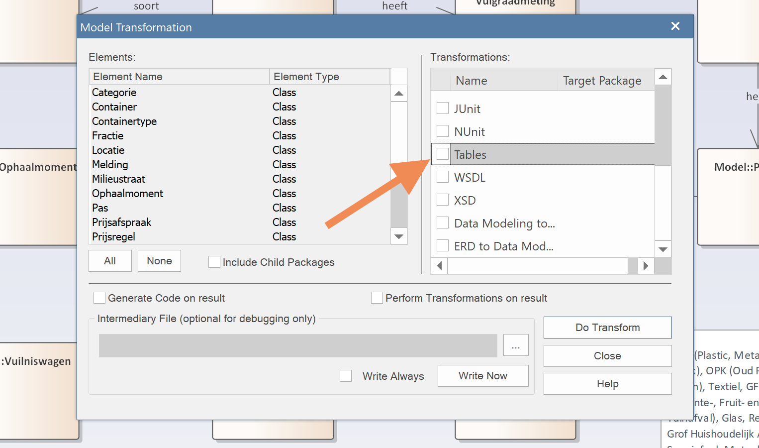
Screenshot: the Transformations dialog with "Tables" selected.
4. In the new Select Target Package popup, select the place you created to write the tables. In our example, <<DataModel>> Tables/Ruimte/Afval.
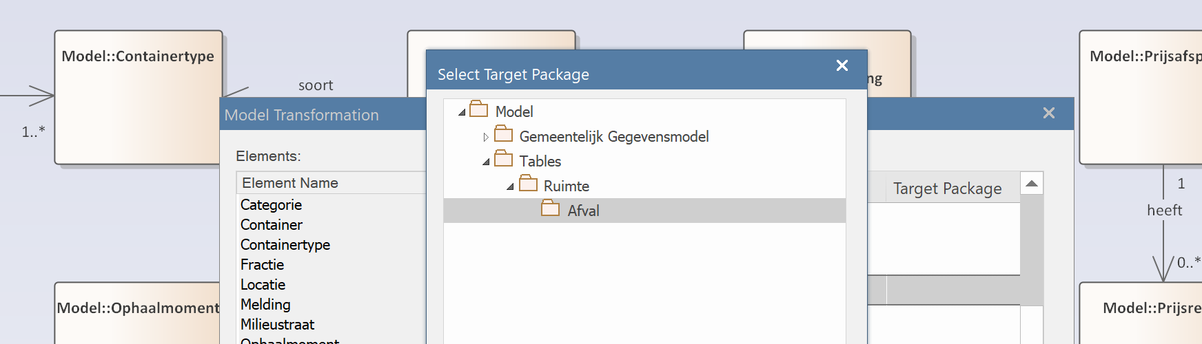
Screenshot: target package selection dialog.
5. To start the first step, click Do Transform.
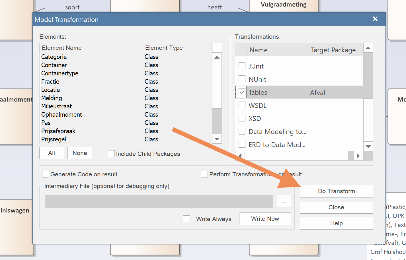
Screenshot: "Do Transform" button highlighted.
6. Wait a moment — the first generation step has been performed: the tables in Enterprise Architect have been created. A "logical" RDBMS-independent version of the tables now exists.
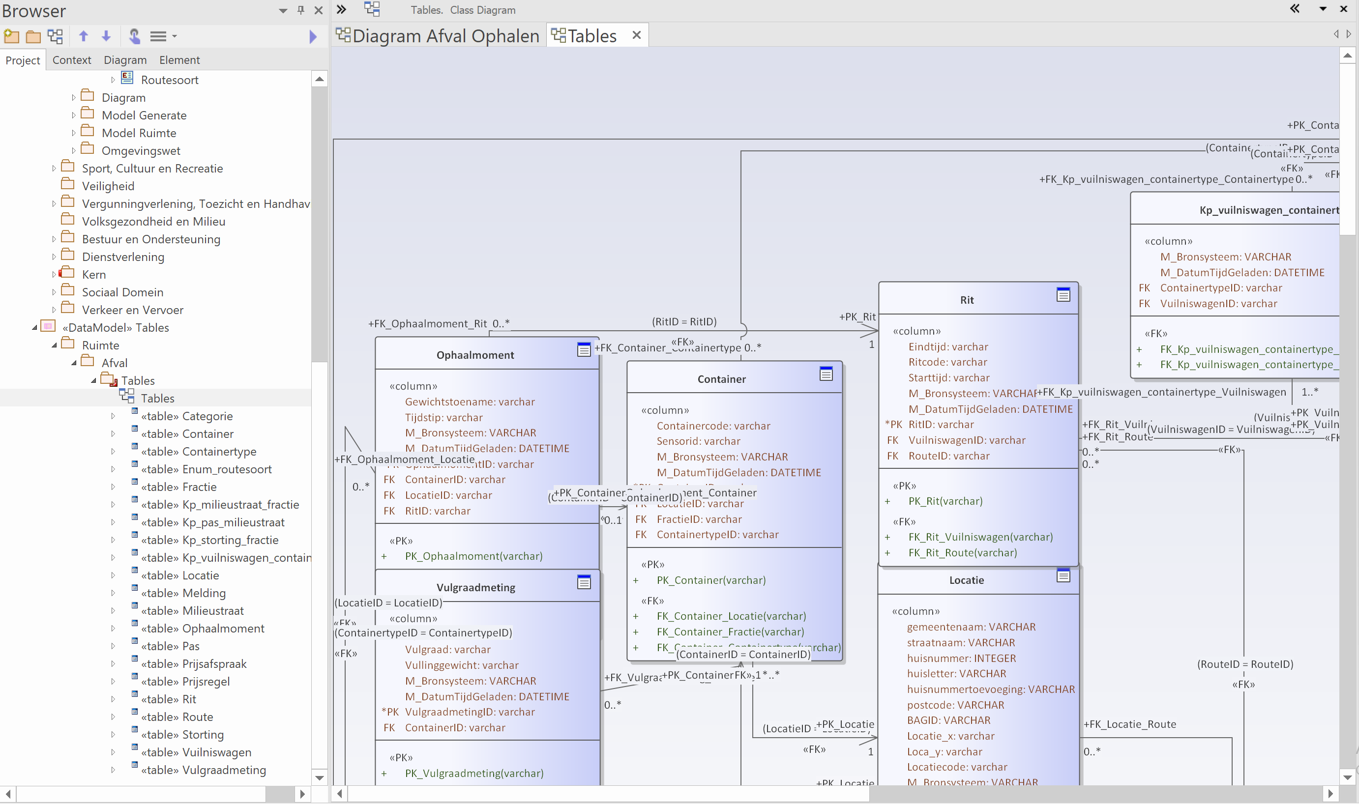
Screenshot: the generated logical tables visible in the Project Browser.
7. In the next step, you generate DDL from the "logical" RDBMS-independent table version. Select the folder containing the tables that were just generated.
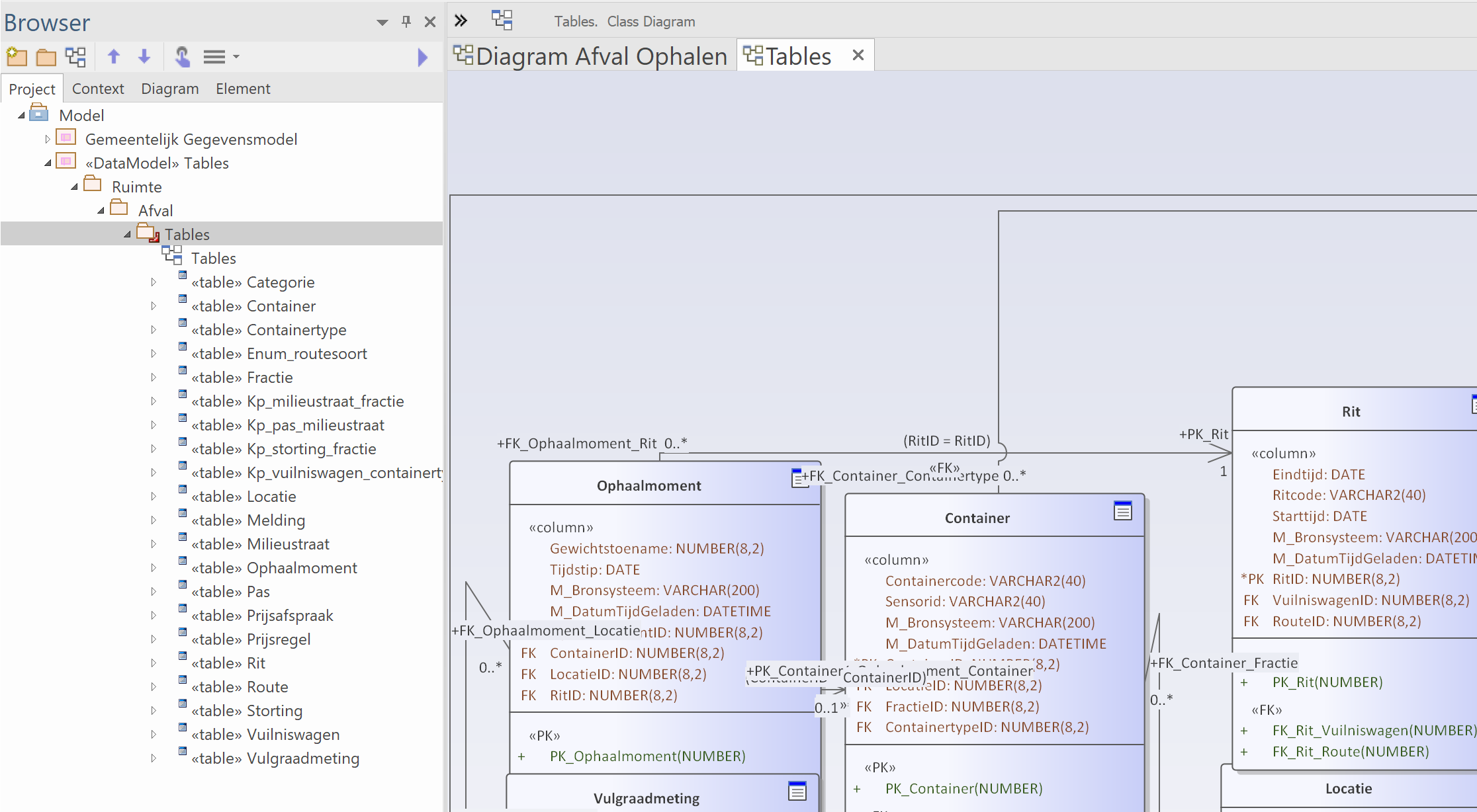
Screenshot: selecting the table folder in the Project Browser.
8. Under Develop / Datamodelling, choose Generate.
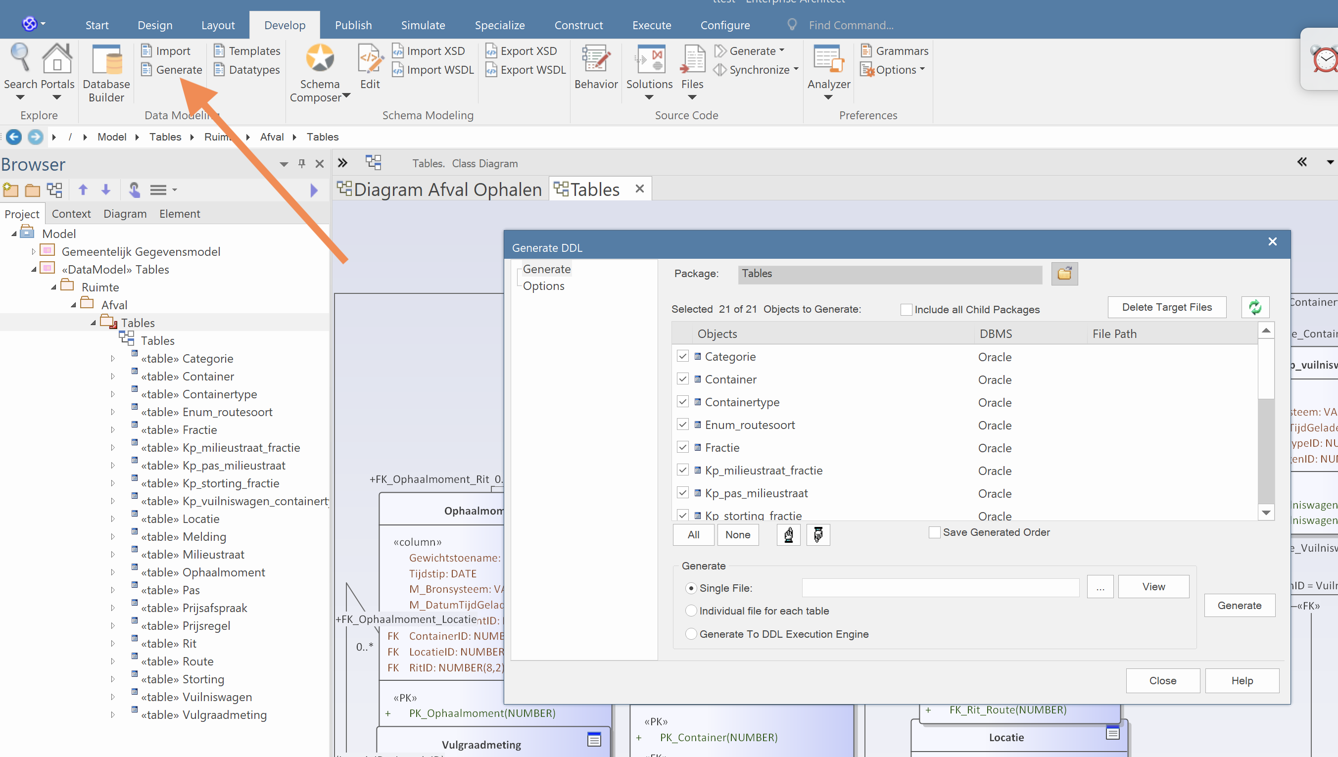
Screenshot: the Generate option in the Datamodelling menu.
9. Enter a file name and folder, and press Generate.
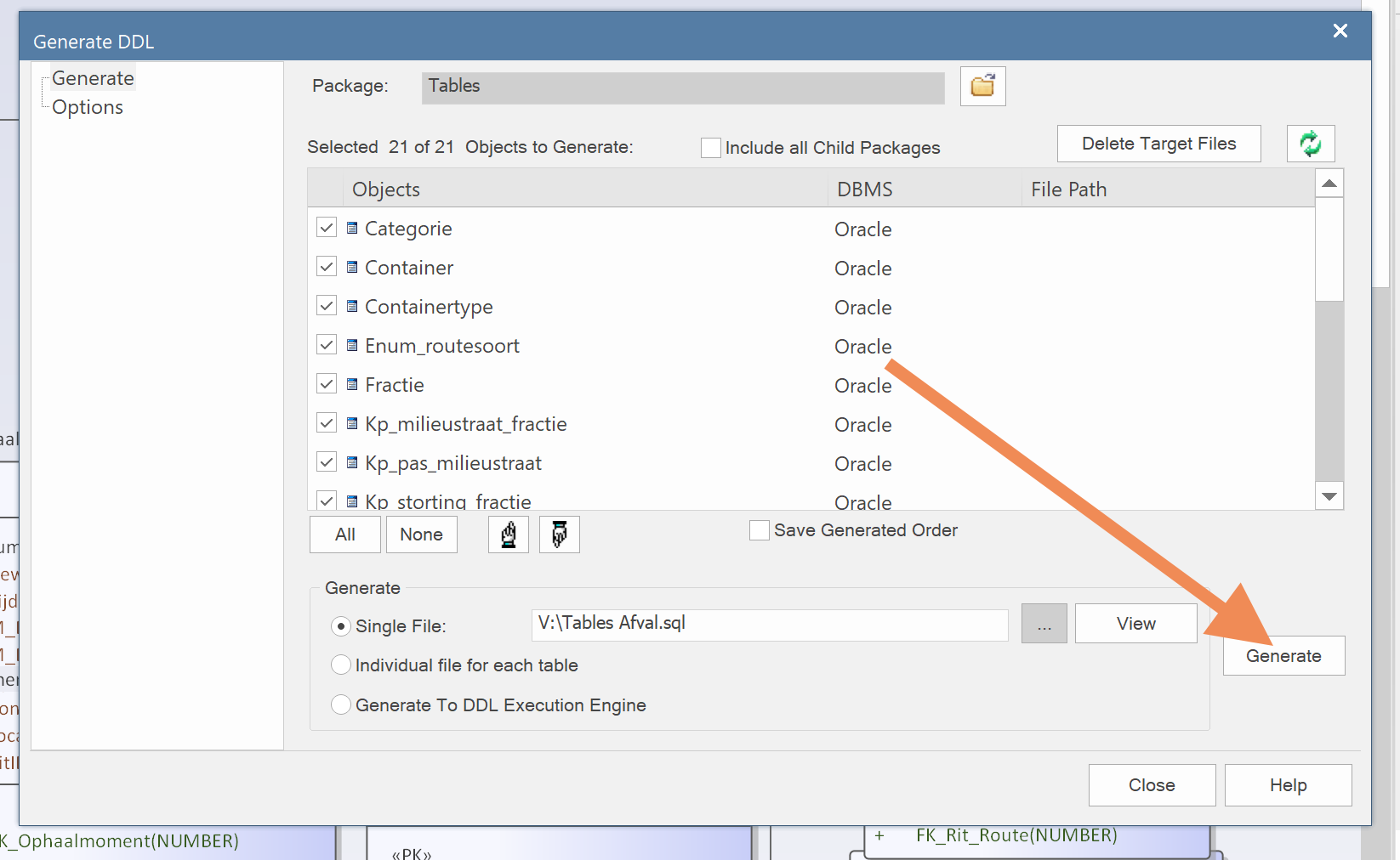
Screenshot: the Generate DDL dialog with file name filled in.
10. Wait a moment — the DDL is ready. Done!
How it works internally
The capabilities of the code-generation templates limit what you can do when modelling in the GGM. Data types and relationships not supported by the templates cannot be (automatically) converted to tables, and cannot be used well when applied. The following describes what you can use in the logical model and how it transforms to tables.
Object types (Classes)
When generating table names, the following order applies (all names are truncated to a maximum of 30 characters):
- Alias
- Object-type name
If the folder containing the object type has an Alias, it is used as a prefix for the table name. In addition, two columns are added to every table (intended to be filled when populating the data warehouse):
DWH_Bronsysteem(name of the source system from which data was loaded)DWH_DatumTijdGeladen(system date/time when data was loaded)DWH_DatumTijdGeldigVanaf(for history: date and time from which the record is valid)DWH_DatumTijdGeldigTotMet(for history: date and time up to and including which the record is valid)
If an object type has a Stereotype, it is used as follows:
-
enumeration(Oracle and MySQL only): converted to a table with a_ENUM_table-name prefix. The table always has the columns: ID, value and description. The various attributes are converted to INSERT statements so the table is filled. Attribute fields map as follows:- ID: attribute field Alias
- value: attribute field Name
- description: attribute field Comment
-
referentielijst: table with table-name prefix_LST_.
Attributes
The code-generation templates convert the various attributes of GGM object types based on Datatype and Stereotype. These extend the Code Template Framework of Enterprise Architect. For attribute (column) names the order is:
- Alias
- Attribute name
Attributes are converted by data type as follows (case-insensitive):
DatumtijdorDatetime: attribute with both date and time (Oracle: DATE field).DatumorDate: date only.TijdorTime: time only.ANxxx: text field (alphanumeric) of length xxx. If no length is given, length 80 is used.IntegerorInt: numeric field (integers only).Double: numeric values with decimals.Bedrag: amount field (max 10 digits, 2 after the decimal).TekstorText: text field for long memo fields.Boolean: Boolean (Oracle numeric field: 'J'=1, 'N'=2, 'Other'=-1, 'Unknown'=null).GUID: text field of 40 characters.GMLorPunt: location — split into two fields for WGS84 coordinates (<fieldname>_latand<fieldname>_long) and two fields for Dutch RD coordinates (<fieldname>_rdxand<fieldname>_rdy). All fields are doubles.
Attributes are converted by Stereotype:
Adresaanduiding(address designation): the field is replaced by: municipality name, street name, house number, house letter, house-number suffix, postal code and BAG ID.enumeration: a reference to the enumeration is included. See Example D.
Relationships
Translating relationships in the logical model is not always straightforward — particularly for the naming of foreign keys and foreign-key constraints. Three examples follow.
Example A
The first example shows 4 object types/classes with three relationships:
- Relationship A: 1:N
- Relationship B: N:M
- Generalisation of Class A relative to Child Class A
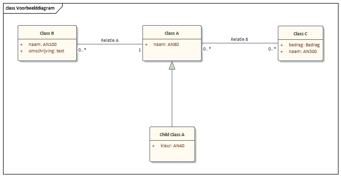
Diagram: four classes with three relationships before transformation to tables.
After transformation, these relationships translate as follows:
- Relationship A: column
ClassAIDin tableClassBwith a foreign key to tableClassA. - Relationship B: a junction table
KP_classa_classcwith foreign-key relationships toClassAandClassB. - Generalisation: the two tables remain separate; columns are not copied into the child. A regular 1:N relationship is created, like Relationship A.
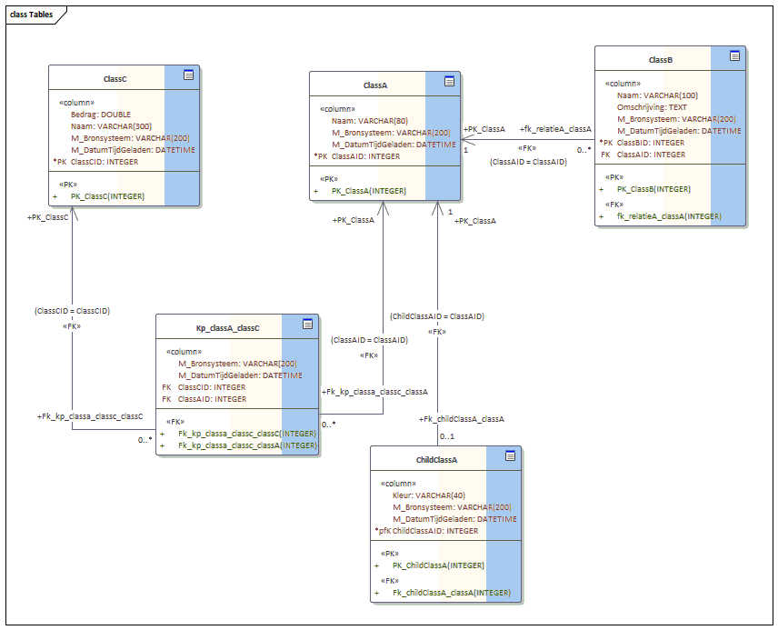
Diagram: the resulting tables with foreign-key columns and a junction table.
Example B
The naming of foreign keys, foreign-key constraints and junction tables can be influenced through relationship names and aliases. This avoids duplicate constraints and unreadable or overly long names. The order used (in priority) is:
- Alias of Source/Target
- Alias of relationship
- Relationship name
- Concatenation of Source and Target names
The example covers:
- Relationship
Class A–Class B: relationship name = "Relatienaam". - Relationship
Class C–Class D: relationship has Alias "Aliasnaam". - Relationship
Class E–Class F: both Source and Target have their own alias. - Relationship
Class G–Class H: relationship has no name and no aliases. - Relationship
Class I–Class J: same as 4 but Source and Target swapped.
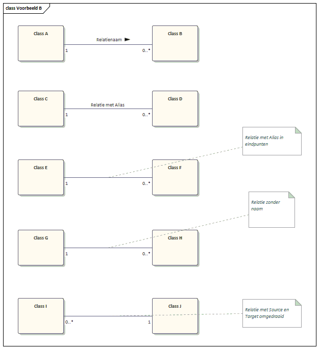
Diagram: the five relationship variants before transformation.
After transformation:
- First: table
ClassAgets columnClassBID(with index) and a foreign-key constraint (using the relationship name) on the relationship toClassB. - Second: table
ClassCgets columnClassCID(with index) and a foreign-key constraint (using the alias) on the relationship toClassC. - Third: table
ClassEgets columnAliasSourceCID(with index) and a foreign-key constraint (using source/target aliases) on the relationship toClassF. - Fourth: table
ClassGgets columnClassHID(with index) and a foreign-key constraint (using table names) on the relationship toClassH. - Fifth: table
ClassIgets columnClassJID(with index) and a foreign-key constraint (using table names) on the relationship toClassJ(same as 4).
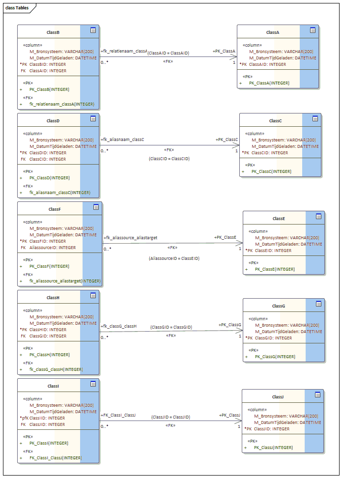
Diagram: resulting tables for the five relationship variants.
Example C
Cases that need special attention because the transformation process otherwise produces errors:
- Self-relationships (e.g. pig sub-type / Varkensoortje).
- Multiple relationships between the same object types.
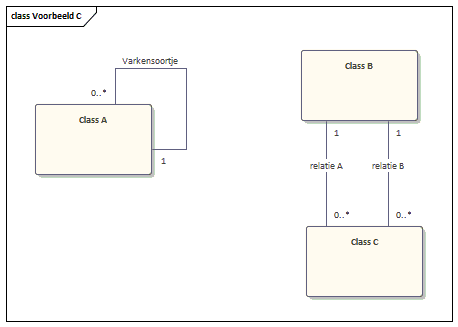
Diagram (in Dutch): the "Varkensoortje" example showing a self-relationship.
To make these work in the transformation, you must provide an Alias on the Source of the relationship. The example shows it for Varkensoortje. You can also use this for multiple relationships. Due to Enterprise Architect's internals, the cardinality on the source side must be 0..1 or 1, otherwise the relationship is not generated correctly.
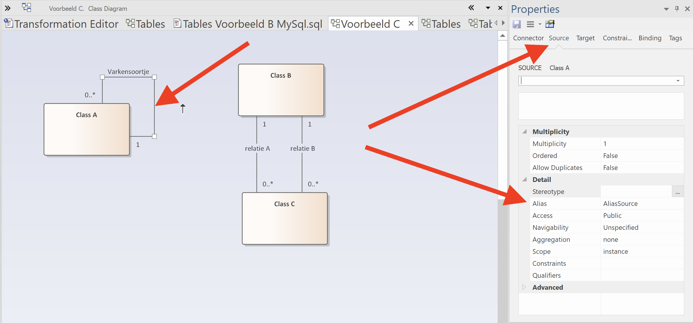
Screenshot (in Dutch / Enterprise Architect UI): setting the Source alias on the self-relationship.
After transformation, the alias is used for the foreign keys and constraints, ensuring unique names.
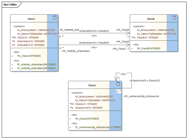
Diagram: the resulting tables with alias-based foreign-key naming.
Example D
Finally, an example with enumerations:
Enumerations are an enumeration of possible values for a given attribute. They allow you to constrain attribute values within a set range in the GGM. To make these work in the transformation process, you must provide an Alias on the Source of the relationship. The example shows it for Varkensoortje; you can also use this for multiple relationships. The following shows how to define an enumeration.
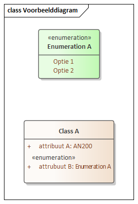
Diagram (in Dutch): an enumeration with two possible values (Optie 1, Optie 2), referenced by attribute B.
The enumeration has two possible values: Option 1 and Option 2; attribute B refers to this enumeration.
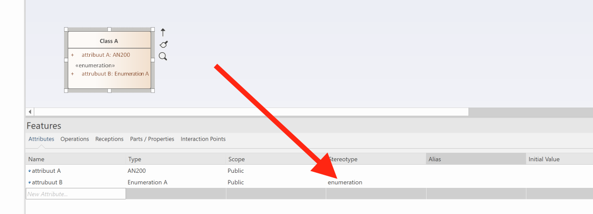
Screenshot (in Dutch / Enterprise Architect UI): linking an attribute to an enumeration via the "enumeration" stereotype.
The screenshot shows how to link an attribute to an enumeration. It is important to set the stereotype value to enumeration.
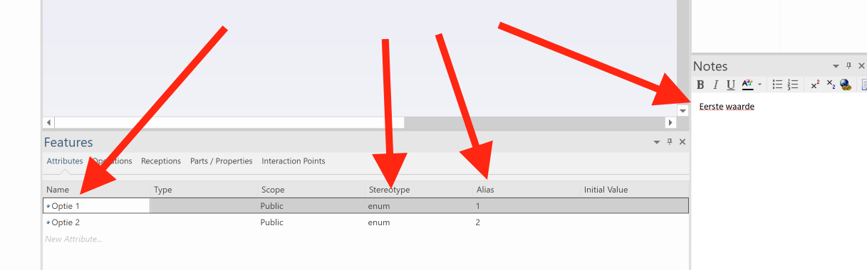
Screenshot (in Dutch / Enterprise Architect UI): defining the value list of an enumeration as attributes.
The figure shows how to define value lists for an enumeration in Enterprise Architect. In the example the value list consists of two values: Optie 1 and Optie 2, defined as attributes of the class Enumeration A. Fill them in as follows:
- Name: in the Name field of the attribute (always fill in to avoid errors).
- Index: in the Alias field (always a unique integer to avoid errors).
- Description: in the Notes field.
- Stereotype: always
enum.
After transformation, both the class and the enumeration become tables, linked by a foreign-key constraint.
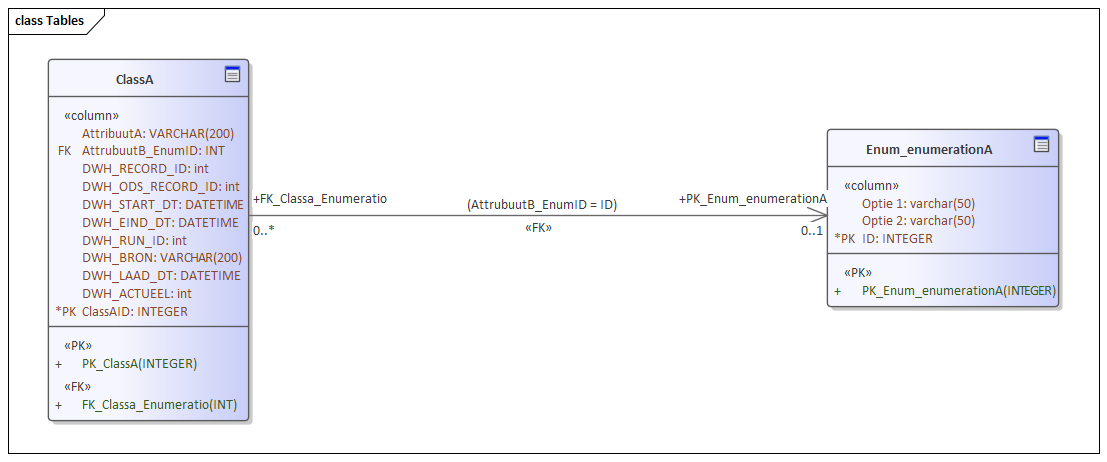
Diagram: the generated tables for the class and its enumeration, linked via a foreign key.
In the generated model, the value lists are still attributes of the enumeration. Only when generating physical database schemas are they converted to value lists in the table.
Customising templates yourself
Once the templates are loaded in Enterprise Architect you can customise them to match your needs. Note that DDL generation runs in two steps, so you can adjust at two levels.
- First step: customise templates that generate database-independent tables.
- Second step: customise the generation of database-independent tables to DDL.
First generation step
Go to Transform templates.
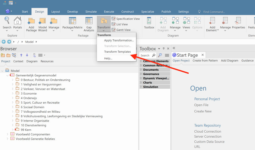
Screenshot: opening the Transform Templates editor.
After opening, choose the language Tables. This collection of templates is used to convert to tables. All template parts used during generation are shown. The next screenshot shows the conversion from a Class.
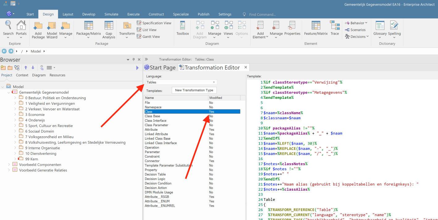
Screenshot: editing the Class-to-Table transformation template.
You are now ready to make your own changes. For more details see the Sparx documentation on transformation templates.
Second generation step
To customise the templates that convert database-independent tables to DDL for specific databases, on the Design tab choose Templates. Once opened, you can pick different database types. The figure below shows Oracle, with the scripts that generate the DDL.
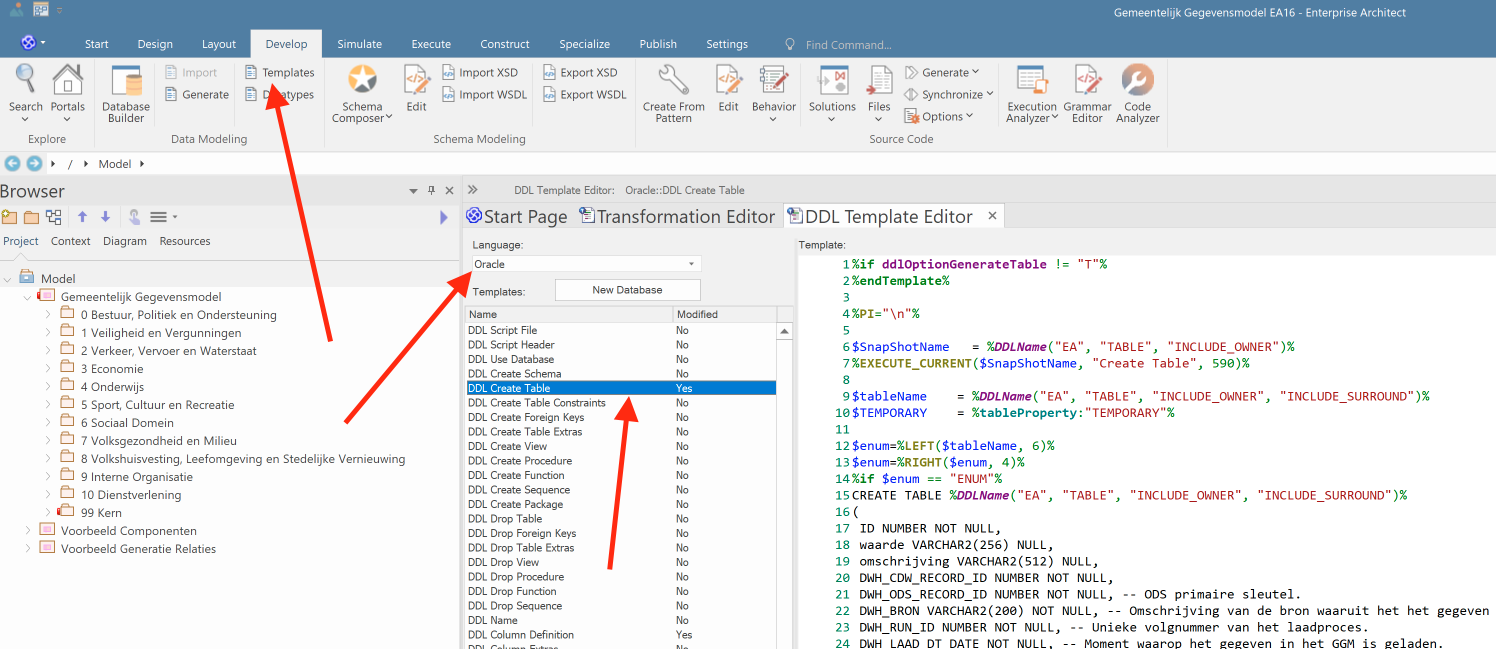
Screenshot (in Dutch / Enterprise Architect UI): the DDL generation templates for Oracle.
We have customised the standard Enterprise Architect behaviour for Oracle and MySQL.